Tools + supplies
- Allen keys
- Soldering iron with M3 insert tip
- Wire stripper / cutter
- Thick CA glue, two-part epoxy, or thickened 3D Gloop
- Hot-glue gun
- Sharp scraping or trimming tool
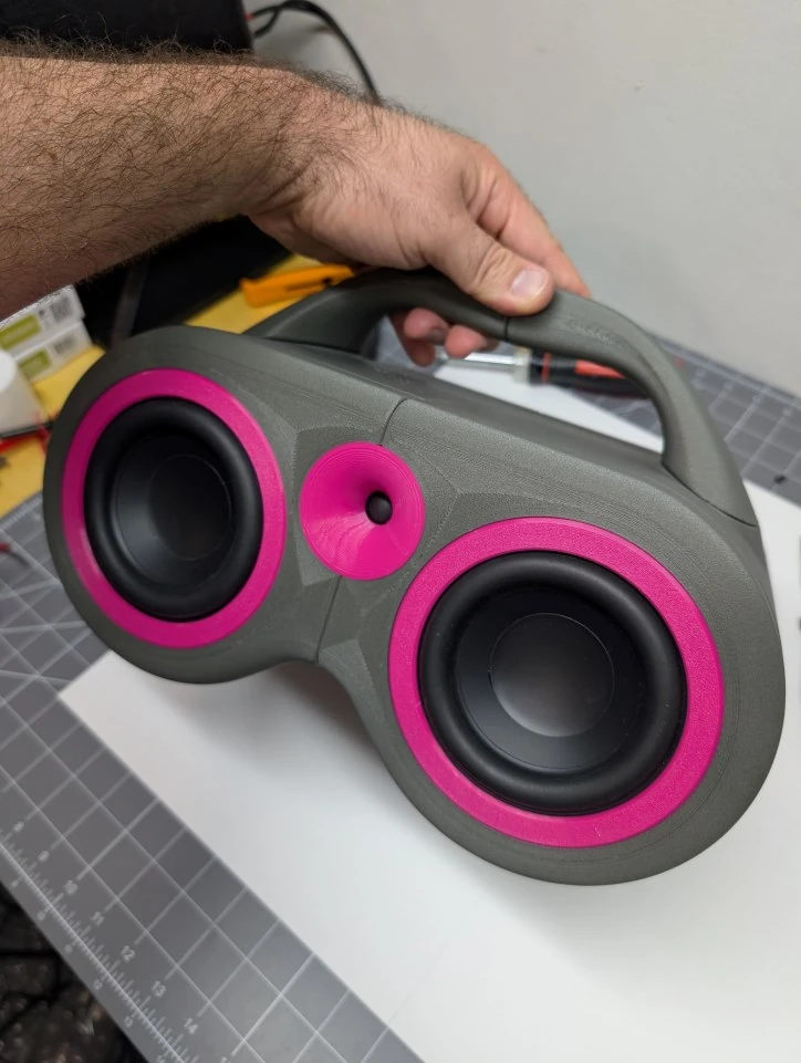
One enclosure. Three configurations. Build a portable Bluetooth speaker, a passive center channel, or a full stereo pair.

Before you begin
The FDMDuo relies on airtight printed joints. Minor gaps are acceptable when adhesive fully wicks against the interior glue fences. Test-fit every component before opening the glue.
PETG, ASA, ABS, and indoor-use PLA are suitable. Fiber-filled filament is recommended for increased stiffness and a refined surface finish.
Kit inventory
Use the table to confirm the parts supplied for your build. Quantities marked with an asterisk should be verified against the final production kit.
| Component | Bluetooth | Center | Stereo pair |
|---|---|---|---|
| Dayton Audio TCP115-8 4-inch woofer | 2 | 2 | 4 |
| Dayton Audio ND16FA-6 soft-dome tweeter | 1 | 1 | 2 |
| Poly-Fil stuffing, 1.5 oz | 1 | 1 | 2 |
| Foam rubber pads | 4 | 4 | 8 |
| M3 x 5.7 brass heat-set inserts | 24 | 24 | 46 |
| M3 x 6 mm button-head bolts | 5 | — | — |
| M3 x 8 mm button-head bolts | 34 | 34 | 46 |
| M3 x 12 mm button-head bolts | 4 | — | — |
| M3 black-oxide nuts | 4 | — | — |
| PCB stand-off kit | 1 | — | — |
| 12-inch 16 AWG two-conductor speaker wire | 3 | 3 | 6 |
| Pink spade connectors | 5 | 5 | 10 |
| Blue spade connectors | 3 | 3 | 5 |
| On/off switch with red spade connectors | 1 | — | — |
| Amplifier-to-battery four-wire connector | 1 | — | — |
| Power jack connector | 1* | — | — |
| Blue LED wire with connector and flange | 1 | — | — |
| Green LED wire with connector and flange | 1 | — | — |
| Four-wire signal cable with bare end | 1 | — | — |
| Binding-post pair | — | 1 | 2 |
| Dayton Audio KAB-100MV2 amplifier board | 1 | — | — |
| Dayton Audio KAB-BE 18650 battery extension board | 1 | — | — |
| Left crossover by MTG Designs | 1 | 1 | 1 |
| Right crossover by MTG Designs | — | — | 1 |
| DTK 19 V x 4.74 A charger | 1 | — | — |
| Lishen 18650 2600 mAh Li-ion three-pack | 1 | — | — |
| 0.5 x 6-inch black hot-glue stick | 1 | — | — |
| Adhesive-backed foam gasket | 1 | 1 | 2 |
Printed part reference
These are the original embedded PDF images extracted cleanly from the guide, without the page text or white page framing.
Gluing guidance
The printed glue fences control alignment and squeeze-out. Review the correct and incorrect adhesive placement before starting the enclosure.
Assembly instructions
Configuration badges identify build-specific steps. Use the thumbnails to navigate each image set, then click the main image to enlarge it.
Glue the rear-baffle sections together, applying adhesive to the ridge shared with the cabinet interior. Join two sections at a time: left to center, then right to center.
Glue the two front-baffle halves together. Apply adhesive to the interior ridge and wick it against the inside of the glue fence. Remove any excess glue from the tweeter opening.
Glue the left and right cabinet halves together, applying adhesive to the interior ridges and faces.
Glue the four printed handle quadrants into two matching halves. Wick adhesive into the internal glue fence and remove squeeze-out.
Glue the two handle halves together at the diamond or square peg-in-hole interface. Use the assembled cabinet temporarily to align the handle while the adhesive cures.
Glue the assembled handle to the cabinet using adhesive only on the inside flats of the cabinet’s raised rings.
Install the brass M3 heat-set inserts in the cabinet rear flange and front-baffle driver flange.
Place the four floating glue-fence segments in the cabinet recess. Apply a liberal bead to the inside edge, then join the front-baffle assembly to the cabinet.
Apply the four adhesive-backed foam pads to the circular recesses on the bottom of the cabinet.
Assemble twelve short stand-off segments and fasten the four stand-off stacks to the rear baffle using the supplied M3 x 6 mm bolts.
Insert the power switch into the largest rear-baffle opening with its two prongs facing the flat edge.
Insert the flanged LED clips into the two smaller holes above the switch. Feed the LEDs through from the cabinet side so the smooth rings face outward.
Secure the charging jack in the opening beneath the power switch.
Apply black hot glue around the power switch, LEDs, and charging jack to create a fillet seal.
Install the three rechargeable cells in the battery extension board, carefully matching polarity. Mount the board with the batteries facing the rear baffle and connect the four-wire extension lead.
Stack the amplifier board above the battery board and secure it with the four silver screws from the stand-off kit.
Connect the four-wire speaker signal cable to Port 1, blue LED to Port 9, green LED to Port 10, and charging jack to Port 2.
Connect the two red spade terminals to the power switch, then connect the cable to Port 7.
Attach the crossover to the rear baffle using the supplied M3 x 12 mm screws and M3 nuts. Install the printed spacer between the crossover and rear baffle.
For center-channel and stereo-pair builds, mount each crossover using the binding posts and printed washers. Remove the non-flanged color ring and align red with positive (+) and black with negative (-).
Twist the two positive leads from the Port 1 signal cable together and repeat with the two negative leads. Insert them into the crossover input screw terminals.
Connect the battery extension cable to Port 6. Turn the speaker on: the blue LED should blink. Connect the charger: the green LED should illuminate steadily. Turn the unit off and disconnect the charger after the test.
Crimp two pink spade pairs for the woofers and one blue spade pair for the tweeter. Connect the bare ends to the LF and HF crossover terminals, maintaining polarity.
Peel and apply the foam gasket around the rear cabinet flange. Butt the square ends together without gaps; overlap is acceptable if excess thickness is trimmed.
Bundle the wiring neatly, align the rear baffle, and fasten it with the M3 x 8 mm screws.
Pull the woofer and tweeter connectors through their openings. Divide the Poly-Fil evenly between both cabinet chambers.
Connect positive-to-positive and negative-to-negative for both woofers and the tweeter. Press the tweeter into its opening and fasten both woofers with M3 x 8 mm screws.
Snap the two woofer accent rings and tweeter waveguide into position. Passive center-channel and stereo-pair builds are now ready to connect to an amplified source.
Place each flat grille in the lower form, warm it evenly with a heat gun until soft, press the upper form into place, flip the assembly, and insert the lower plug until the plastic cools.
Power on the speaker. The blue LED should flash while discoverable. Select “DAKAB” on the phone or Bluetooth source; the LED should become steady after connection.
Build complete
Passive builds can connect to an amplified source after Step 27. Bluetooth builds should appear as DAKAB when ready to pair.